Figure 4 graphically shows how a bridge-like shape is processed and evaluated based on user-defined sensitivity levels. In this example, the width of the gap region of interest is determined by the opening geometry of the template. From a design perspective, this is logical because there should be no solder paste in the area between the openings, along with good and clear printed graphics. As an additional precautionary measure, the gap area is slightly enlarged to calculate any area of ​​the solder paste that may extend beyond the ends of the opening.
The bridge-like shape shown in FIG. 4 is very fine and difficult to detect with the naked eye. Although the solder paste spans the width of the entire gap, the area of ​​the solder paste in the total gap is still very small. In fact, the total paste area is less than 10%, or well below any practical limit, which avoids false alarms due to optimal process changes. This highlights the need for detection and accurate measurement of the effective span of the solder paste geometry across the gap, and also because of the individual area measurements, which clearly provide the ability to complete bridging detection or preventative analysis.
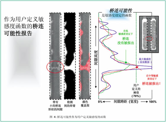
In FIG. 4 , the gray solid line (blue curve in the figure) is a hatched line image of the unprocessed solder paste image data along the bridge axis. In a paste-only image, the high probability area of ​​the solder paste may be displayed as white while the area of ​​"low" probability is displayed with a correspondingly weighted gray scale gradient. To extend any part of the section line to the opposite side of the drawing, all "solder paste" pixels must be full. In other words, they are the most likely to be solder paste. Even then, in some cases, a complete leap may consist of a single bridging solder paste filament with indeterminate defect initiation. For the purpose of applying automatic defect detection to printing operations and subsequent related assembly processes, it becomes impractical to use unprocessed or "unconditional" paste image data directly.
In contrast, the black (red line in the figure) dashed line shows the equivalent section line obtained on the same solder paste shape under the “middle†sensitivity, a relative setting that will be selected for more Weights are added to shapes with more bridging geometry, while “small†weights are added to fewer, beam-like bridge-like shapes.
The grey (dotted green curve on the right in the figure) dashed line shows the equivalent profile and bridging possibilities obtained at the “low†grade sensitivity—effective measurements are only made for shapes that have large defects.
The user-defined span line, or threshold, is shown with a vertical dashed line at 70%. Therefore, in this example, based on user-defined sensitivity settings, this bridge-like shape may be reported as an obvious potential defect or not reported. In any case, data will be collected for trend analysis and SPC.
The detection of large and very obvious bridge-like shapes is seldom affected by user-defined sensitivity settings, which facilitates the detection of higher consistency for these large shapes. As mentioned before, there is no measurement method or precise positioning method that can determine whether a “short circuit†will or will not occur at a certain position after reflow, but its probability can be predicted by this system and Given, and the system can be adjusted to the best state that the user needs.
Wire Mesh & Wire Series,Metal Mesh,Chicken Wire Mesh,Stainless Steel Mesh
Anping County Hua Guang Wire Mesh Production Co.,Ltd , https://www.hgwirefence.com